Pathfinding and AI in Unity
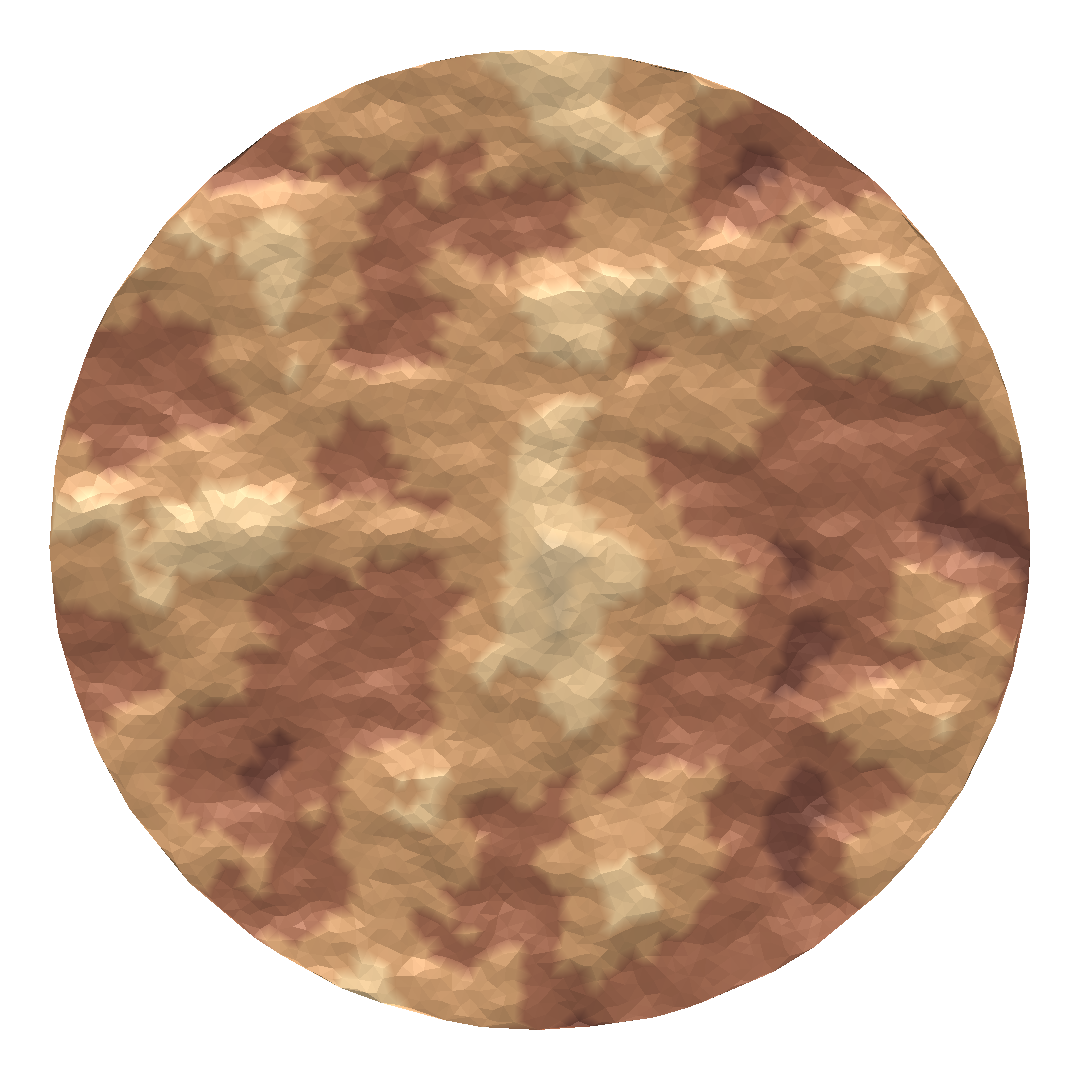
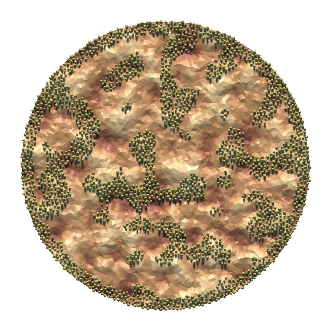
29 Oct 2024Following my experiments with procedural map generation, I wanted to see some action on the maps I generated. So, I decided to add agents to the scene to observe how they navigate through the map. And, in order to make it look more interesting, I wanted the agents to behave intelligently and perform certain tasks.
For navigation, I decided not to use Unity’s AI navigation package because I wanted to implement it myself. I specifically wanted to learn about the A* pathfinding algorithm and integrate it into my project. I found this amazing video series by Sebastian Lague to learn how to implement the algorithm. Since my terrain was created from point samples generated by Poisson Disk Sampling, it wasn’t a grid, so I needed to adapt the code in the tutorial to arbitrary graphs. The transformation seemed straightforward: the most noticeable difference between a grid, which is a special kind of graph, and the graph that represented my procedurally generated terrain was that the nodes in my graph can have arbitrary number of neighbors. However, it wasn’t going to be that simple, because the game’s poor performance in the case of many pathfinding requests would force me to parallelize pathfinding.
Running pathfinding tasks in parallel implied that I had to use Unity’s job system to enable multithreaded code execution. This meant that I had to convert my A* pathfinding implementation to a struct that implemented the IJob interface. In addition to this, I had to get rid of all the managed (≈ garbage collected) objects that the job used and switch to thread-safe types because the Burst compiler doesn’t support managed types.
The first change I made was to convert the managed node class that represented the vertices of my graph to a struct. Since the terrain is generated at the start of the game and it remains the same throughout runtime, the node positions could be made read-only. For pathfinding, I only needed to use the position on the xz-plane since the point samples were initially contained within a 2D disk on this plane and later assigned an elevation (y) value using Perlin Noise. I also needed the 3D positions of the nodes for placing objects at these locations. So, I decided to declare three fields (x, y and z) and define two properties (Pos2 and Pos3) that would return the 2D and 3D positions, respectively. In addition to the coordinates and positions, I also added an index field to facilitate the lookup of nodes. The GraphNode struct ended up looking like this:
public readonly struct GraphNode : IEquatable<GraphNode> {
  public readonly int index;
  public readonly float x;
  public readonly float y;
  public readonly float z;
  public readonly Vector2 Pos2 => new(x, z);
  public readonly Vector3 Pos3 => new(x, y, z);
  public readonly bool Equals (GraphNode other) => index == other.index;
  // ...
}
The A* pathfinding algorithm requires three values: g is the cost from the start node to the current node, h is the heuristic cost from the current node to the end node, and f is the sum of g and h. It begins by exploring the neighbors of the start node and stores them in the open list, sorted by their f values in an ascending order (lowest f cost first). A node whose every neighbor has been visited is moved to the closed list. Then, a new node is taken from the open list until the end node is added to the closed list. If the algorithm discovers a shorter path to any node in the open list during its execution, it updates the g cost of that node which results in an updated f cost. Hence, the open list should be able to efficiently reorder the nodes in the case of an update, which I will discuss later. For the algorithm to be able to trace the path backwards to construct the path after the end node has been reached, each node must point to the neighbor with the lowest g cost to indicate which step was taken; hence, another field (named parent) is required to store a reference to this neighboring node. Remember that this reference cannot be a pointer to a class instance since we’re not allowed to use managed types.
You may be wondering why I didn’t include the cost fields in the GraphNode struct. Notice that these costs are different for every pathfinding request that has a different start and end point, which means every job needs its own copy of the graph. Remember that the terrain, hence the node positions, is the same for each job. Storing both the positions and the costs in the same struct would result in unnecessary duplication of the coordinate values which did not change. So, it made more sense to define a separate struct to store the costs and other pathfinding related data that differed from job to job. The nodes that stored the positions could be shared between jobs (more on that later). With the addition of couple other fields that are implementation specific, the PathNode struct turned out like this:
public struct PathNode : IEquatable<PathNode>, IComparable<PathNode> {
  public readonly int index;
  public int parent;
  public bool isExplored;
  public bool isObstacle;
  public float g;
  public float h;
  public readonly float F => g + h;
  public readonly bool Equals (PathNode other) => index == other.index;
  public readonly int CompareTo (PathNode other) => other.F.CompareTo(value: F); // reverse the order so that lower F means higher priority
  // ...
}
The index value of a PathNode must be equal to the index of the corresponding GraphNode for convenience. The parent field is an integer that is the index of the neighboring node where a candidate path passes through. Even though I wanted to use a set to store the explored nodes (or indices), I opted to add a field called isEplored to indicate if a node has been explored, which I will explain later. I also added a field called isObstacle to indicate if the node is an obstacle because the map could contain trees. But the map was not supposed to change, hence the tree positions; so, why not include this field in the GraphNode struct? Because, tree positions are determined at a later stage after the nodes are constructed, and I thought I could add dynamic obstacles to the scene in the future. The CompareTo method of the IComparable interface for the float type in the expression a.CompareTo(b) returns greater than 0 if a is greater than b and vice versa; it returns 0 if they are equal. In my open list implementation, I sort items based on priority in a descending order (highest priority at the top). So, I implemented the CompareTo method in a way that returns greater than 0 when a has a lower f cost (higher priority) than b.
Now, it’s time to clear up the things I left unexplained in the preceding paragraphs. They are either related to the native container types that come with the Collections package or custom containers created by myself. These containers are thread-safe and can be used for data that is shared between a worker thread and the main thread.
Recall that the graph, which represents the terrain, is constant and can be shared between threads. NativeArray is the container I used to store GraphNode instances that constitute the terrain. This same array (graphNodes) is passed to the constructor of each PathfindingJob instance that is created. For this to work properly, and to receive appropriate warnings/errors when a job attempts to write to this container, it is required to add the ReadOnly attribute before the field declaration in the job definition that references this graph. The array itself is created by the main thread in a MonoBehaviour instance which is also responsible for disposing of it (by calling its Dispose method) once it’s no longer needed, to prevent memory leaks. This array is created using the Persistent allocator since its lifetime exceeds the four frame limit of the TempJob allocator. The edges of this graph are stored in a NativeParallelMultiHashMap of type <int, int> where the key is the index of a node and the value is a set that contains the indices of the node’s neighbors. This structure (graphEdges) is also created and handled the same way graphNodes is.
There can also be containers that are local to the job struct. These are allocated and deallocated by the job itself. Remember that the open list had to efficiently sort and store the PathNode instances. The pathfinding tutorial by Sebastian Lague also touches on this topic, and the data structure that is used for this job is a heap, specifically a max heap since higher priority nodes are at the top of the heap. However, the implementation in the tutorial could not be used in a job since it must be a native container. So, I had to convert that implementation to a NativeHeap by looking at the examples, and I was successful in doing so after some trial and error. The constructor of this custom native container looks like the following.
[NativeContainer]
[NativeContainerSupportsDeallocateOnJobCompletion]
public unsafe struct NativeHeap<T> : IDisposable where T : unmanaged, IEquatable<T>, IComparable<T> {
  public NativeHeap (int initialCapacity, Allocator allocator) {
#if ENABLE_UNITY_COLLECTIONS_CHECKS
    m_Safety = AtomicSafetyHandle.Create();
    AtomicSafetyHandle.SetStaticSafetyId(handle: ref m_Safety, staticSafetyId: s_staticSafetyId);
    AtomicSafetyHandle.SetBumpSecondaryVersionOnScheduleWrite(handle: m_Safety, value: true);
#endif
    capacity = initialCapacity;
    if (capacity <= 0)
      capacity = 16;
    m_Length = 0;
    m_AllocatorLabel = allocator;
    m_Buffer = (T*)UnsafeUtility.MallocTracked(size: capacity * UnsafeUtility.SizeOf<T>(), alignment: UnsafeUtility.AlignOf<T>(), allocator, callstacksToSkip: 1);
  }
  // ...
}
It is possible to add the DeallocateOnJobCompletion attribute before the declaration of the field of type NativeHeap in the job struct so that the job system automatically deallocates the container when the job is finished. For this to work, the custom container implementation must have the NativeContainerSupportsDeallocateOnJobCompletion attribute and comply with the requirements specified in the description page of this attribute. Recall that I had to add a field called isEplored to the PathNode struct because I could not use a NativeHashSet for the closed list. The reason is that this native container does not support the DeallocateOnJobCompletion attribute, and I did not want to manually dispose of it inside the Execute method of the job to keep it clean of code that is not directly related to the pathfinding algorithm itself. The fields of PathfindingJob are as follows:
public struct PathfindingJob : IJob {
  [DeallocateOnJobCompletion] NativeHeap<PathNode> queue;
  [ReadOnly] readonly NativeArray<GraphNode> graphNodes;
  [ReadOnly] readonly NativeParallelMultiHashMap<int, int> graphEdges;
  NativeArray<PathNode> pathNodes;
  NativeList<GraphNode> path;
  readonly PathEndpoints endpoints;
  // ...
}
The PathEndpoints struct is a pair of integers that specify the start and end node indices. The path is a NativeList created outside the job and filled in during its execution. It is not created in the job’s local scope so it can be accessed later, after calling Complete on the JobHandle. The queue is the open list, which is a priority queue implemented as a heap.
Before diving into how the pathfinding requests are handled, it is necessary to describe how they are created. These requests come from agents that display intelligent behaviour such as following other agents and destroying them, which brings us to artificial intelligence, but not in the form of a neural network. I wanted something simple since the behaviour I wanted to observe consisted of a few basic actions. I found behaviour trees to be more suitable in my case compared to state machines or goal oriented action planning. I’ve found this nice tutorial by Mina Pêcheux to learn about the basics and see how it’s implemented. My implementation looked more or less the same: I defined a LeafNode class and two composite node classes (SelectorNode and SequenceNode) that extend this class. To facilitate passing of data between the nodes of a behaviour tree, I implemented a basic Blackboard class and let all the nodes refer to a common instance. This class defines two dictionaries, one for the information that is being stored and one for the observers that will be notified when certain information is updated. I limited the number of observers for each key to one, which was enough for my purposes.
public sealed class Blackboard {
  readonly Dictionary<string, object> data = new();
  readonly Dictionary<string, Action> subs = new();
  public void Subscribe (string key, Action callback) {
    if (!subs.ContainsKey(key))
      subs[key] = null;
    subs[key] += callback;
  }
  public void Unsubscribe (string key, Action callback) {
    if (subs.ContainsKey(key))
      subs[key] -= callback;
  }
  // ...
}
The root node of an agent’s behaviour tree is a SequenceNode which has four children that define all the actions that an agent can perform. These actions are detecting a target, finding a path to the target, moving towards the target by following the path, and attacking the target. They are evaluated in sequence, and if any one of them does not succeed, the remaining nodes are skipped. These behaviours are all defined in separate classes that extend the LeafNode class. This tree is evaluated in the Update method of the agent’s MonoBehaviour class. The Start and Update methods of this class are given below.
public sealed class AgentBehaviour : MonoBehaviour {
  // ...
  void Start () {
    var detectTarget = new DetectTarget(blackboard, transform, getClosestEnemy: playerEvents.GetClosestEnemy, scanInterval: gameSettings.targetScanInterval);
    var findPath = new FindPath(blackboard, transform, requestPath: playerEvents.RequestPath);
    var followPath = new FollowPath(blackboard, transform, moveSpeed: gameSettings.unitMoveSpeed, attackRange: gameSettings.unitAttackRange);
    var attackTarget = new AttackTarget(blackboard, transform, attackRange: gameSettings.unitAttackRange, initiateAttack: playerEvents.InitiateAttack);
    behaviourTree = new SequenceNode(blackboard, detectTarget, findPath, followPath, attackTarget);
  }
  void Update () {
    behaviourTree.Evaluate();
  }
}
Here, gameSettings and playerEvents are ScriptableObject instances that store the game parameters and gameplay related actions, respectively. Agents need to trigger certain actions to perform some of their tasks that require collaboration from other scripts. For example, they do not know about each other by design; hence, they have to trigger an Action at a fixed interval (unless there is already a valid target) in order to get the Transform component of the enemy that is closest to them. As a result, these delegates are passed to any tree node that needs to trigger them. One such action is RequestPath of type Action<Vector2, Vector2, Action<GraphNode[]>> that is defined in PlayerEvents. Here is the FindPath node where these requests are made:
public sealed class FindPath : LeafNode {
  // ...
  public FindPath (Blackboard blackboard, Transform transform, Action<Vector2, Vector2, Action<GraphNode[]>> requestPath) : base(blackboard) {
    // ...
    blackboard.Subscribe(key: "Destination", callback: OnDestinationUpdated);
  }
  ~FindPath () {
    blackboard.Unsubscribe(key: "Destination", callback: OnDestinationUpdated);
  }
  void OnDestinationUpdated () {
    pathFound = false;
    findPath = true;
    destination = blackboard.GetData<Vector2>(key: "Destination");
    var pos2 = new Vector2(x: transform.position.x, y: transform.position.z);
    requestPath?.Invoke(pos2, destination, OnPathFound);
  }
  void OnPathFound (GraphNode[] path) {
    findPath = false;
    pathFound = true;
    blackboard.SetData(key: "Path", value: path);
  }
  public override NodeState Evaluate () {
    if (pathFound)
      return NodeState.Success;
    if (findPath)
      return NodeState.Busy;
    return NodeState.Failure;
  }
}
Now, let’s see how these requests are handled. The RequestPath invocation requires three arguments: agent position, target position and a delegate to the method that will process the returned path. At the receiving end of these requests, there is a queue that stores them. This is crucial because attempting to process all the requests as they arrive would cause poor performance when there are many such requests in the duration of one frame. Instead, they are processed in batches such that in each frame at most n requests are removed from the queue and n pathfinding jobs are run. The following code schedules jobs that will be executed in parallel by worker threads on multiple CPU cores. A copy of the pathNodes is created for each job since it contains information about the obstacles on the terrain. For the special case of batch size of one or a queue with only one item (not included in the code below), the Temp allocator is used over TempJob for faster allocation, and the job is directly executed (not scheduled).
var numJobs = Mathf.Min(a: gameSettings.pathfindBatchSize, b: pathRequestQueue.Count);
var jobData = new List<(JobHandle handle, NativeArray<PathNode> pathNodes, NativeList<GraphNode> path, Action<GraphNode[]> handler)>();
for (var i = 0; i < numJobs; i++) {
  var (endpoints, handler) = pathRequestQueue.Dequeue();
  var path = new NativeList<GraphNode>(allocator: Allocator.TempJob);
  var pathNodes = new NativeArray<PathNode>(length: this.pathNodes.Length, allocator: Allocator.TempJob);
  pathNodes.CopyFrom(array: this.pathNodes);
  var job = new PathfindingJob(graphNodes, graphEdges, pathNodes, endpoints, path, allocator: Allocator.TempJob);
  var handle = job.Schedule();
  jobData.Add(item: (handle, pathNodes, path, handler));
}
for (var i = 0; i < jobData.Count; i++) {
  var (handle, pathNodes, path, handler) = jobData[index: i];
  handle.Complete();
  pathNodes.Dispose();
  var pathArr = path.AsArray().Reverse().ToArray();
  path.Dispose();
  handler?.Invoke(obj: pathArr);
}
When the path is returned to the FindPath node that requested it, it is written to the blackboard which notifies the FollowPath node. Then, the agent is moved towards the position of the next GraphNode in the path at a constant speed, and this is repeated until it reaches the position of the last node in the array. Index 0 in the path array is the start node which points to the current position of the agent, so the next index should be set to 1 for each new path. If the target is also moving, which is the case here, the path will become invalid as the target starts to get farther away. There is a simple check to determine if the path the agent is currently following will lead to the enemy: calculate the distance from the final node in the path to the enemy and compare it to the distance from the agent’s current position to the enemy, if the final node is not closer to the enemy, request a new path. The Evaluate method of the FollowPath is given below with some parts omitted; attackRange is used as the epsilon value for distance comparisons.
public override NodeState Evaluate () {
  if (path == null)
    return NodeState.Failure;
  var pos3 = transform.position;
  var pos2 = new Vector2(x: pos3.x, y: pos3.z);
  if (target != null) {
    // check if the target is getting away, request a new path if that's the case
  }
  if (nodeIndex > lastIndex)
    return NodeState.Success;
  moveVector = (path[nodeIndex].Pos3 - pos3).normalized;
  transform.Translate(translation: moveSpeed * Time.deltaTime * moveVector);
  if (Vector2.Distance(a: pos2, b: path[nodeIndex].Pos2) < attackRange)
    nodeIndex++;
  return NodeState.Busy;
}
Battles between agents are simulated by one script that stores a dictionary whose keys are the Transform components of the agents in the scene, and values are AgentData instances that contain agent stats such as health points or attack power. When an agent gets close enough to its target, it can initiate an attack by triggering the InitiateAttack action which accepts the Transform components of the attacker and the defender, respectively. Unlike pathfinding requests, battles are not queueed or executed in batches since they are not computationally heavy. Each battle is started via StartCoroutine calls and executed over multiple frames. The attacker gets to hit first, then they take turns. The expression that calculates the damage dealt by the attacker can become very complex as the number of parameters (stats, items, powerups, etc.) increase. If the HP of one side drops to zero, the other side wins. The Fight method that is run as a coroutine is given below.
IEnumerator Fight (TransformPair pair) {
  var attacker = agents[key: pair.A];
  var defender = agents[key: pair.B];
  while (attacker.healthPoints > 0 && defender.healthPoints > 0) {
    var damage = Mathf.RoundToInt(f: attacker.attackPoints * (1f / (defender.defensePoints + 1)) + 1);
    defender.healthPoints -= damage;
    (attacker, defender) = (defender, attacker);
    yield return null;
  }
  battles.Remove(item: pair);
  agents[key: pair.A] = attacker;
  agents[key: pair.B] = defender;
  var loser = attacker.healthPoints > 0 ? pair.B : pair.A;
  // ...
}
The pairings are stored in a HashSet called battles to avoid duplicates. However, representing the fighting pairs as a Tuple would result in (a, b) and (b, a) being treated as different battles, where a and b are Transform instances. To prevent this, I defined a new type called TransformPair that produces the same hash code for the same pair regardless of the order. Once the loser is decided, its entry is removed from the dictionary agents, then it can be destroyed or returned to its pool if object pooling is employed (e.g., if there is re-spawn mechanic).
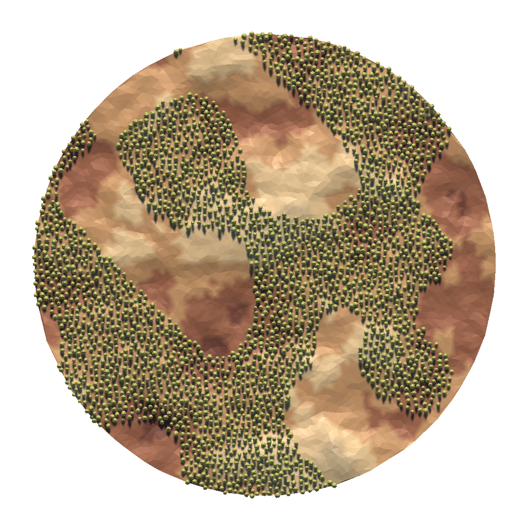
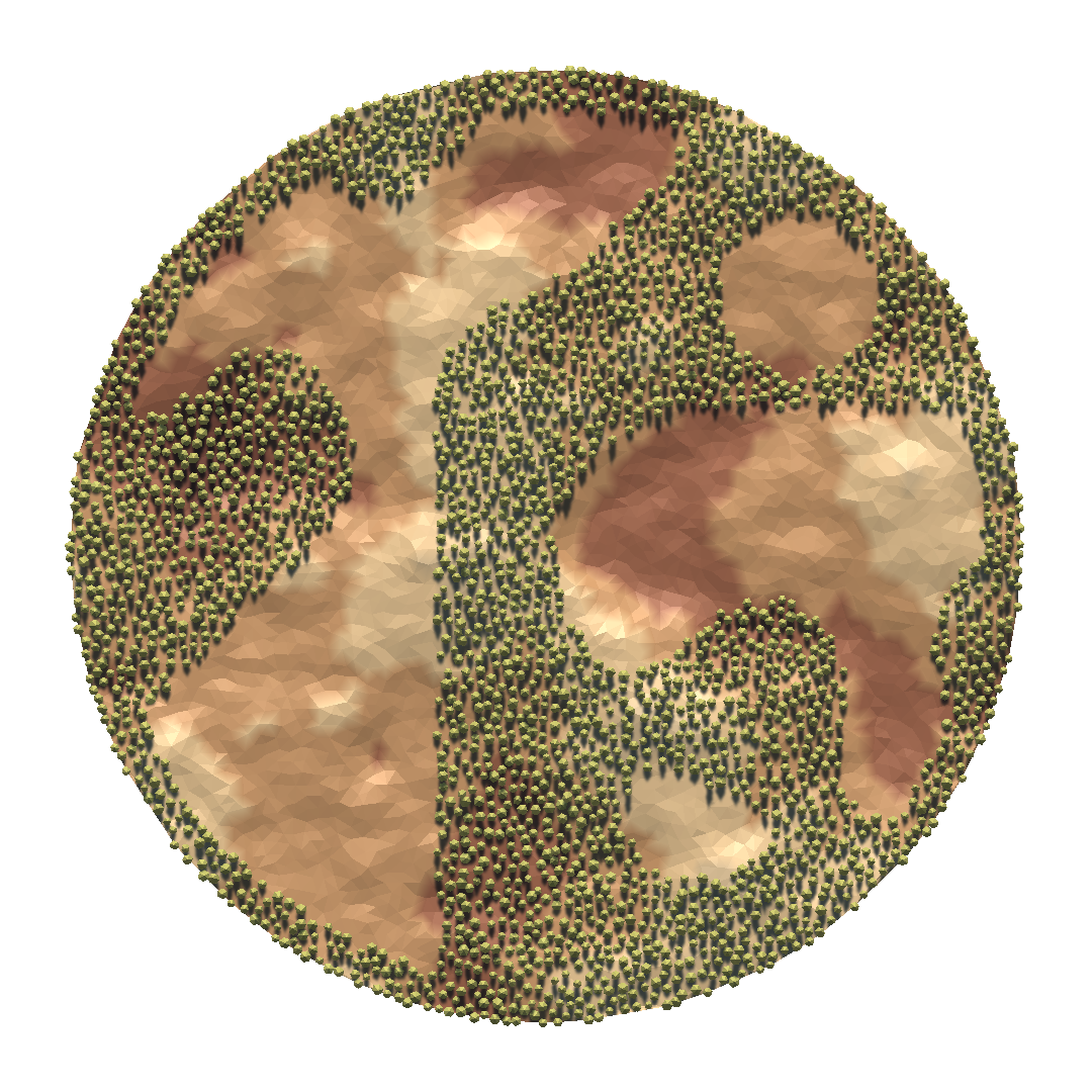
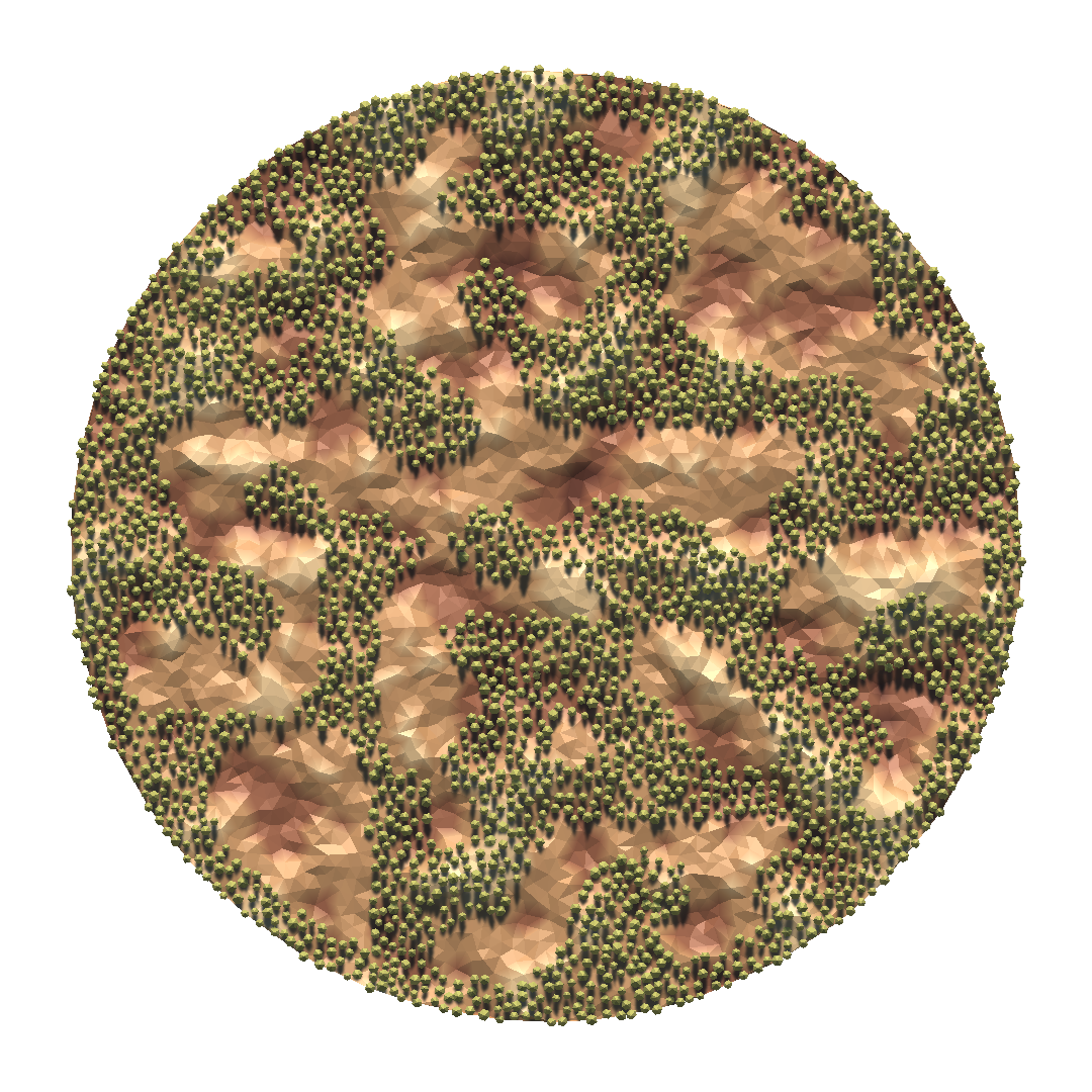
To demonstrate the things I covered in this blog post, I spawned 48 agents at random positions and let them perform the actions defined by their behaviour trees. To make the scene prettier, I used tree models from the Low Poly Tree Pack package. The agents in the following scene are rendered via DrawMeshInstanced calls, similar to how I render the trees.